I have been experimenting with time lapse photography, and quite like doing it. It lends a new perspective to how short time actually is.
Upon further search, some of these pan and tilt devices are used for time lapse photography (one of the popular devices is the Emotimo TB3). With them, you can create shots such as this -
It was the light from Jeff Morris on Vimeo.
I thought that being able to make those kinds of shots would be... awesome. Unfortunately, there were a couple drawbacks to the Emotimo TB3 (the only thing within my price range)
1. I couldn't use it for gigapixel photography (due to nodal point issues)
2. I (as a student) could not afford it.
3. It probably wouldn't be able to do real-time video very well due to the large gearing reductions.
So I set out to build my own.
One of the designs I found to be very helpful was Steven Brace's pan and tilt device, made from acrylic (stevenbrace.co.uk)
Well, the first time I tried building it using laser cut acrylic pieces and acrylic glue. As soon as I tightened the bolt with the gear, the acrylic cracked. Not good.
After that design was thrown out, I decided to base it more off the Emotimo TB3, using machined aluminum. I realized this was not going to work and also scrapped that idea.
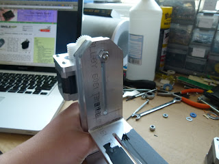
This is where I am today, with machined aluminum struts that are bent into an L shape.
 |
| The Arduino Uno running a Stepstick motor driver |
 |
| The Double L strut design |
 |
| Gearing |
 |
| Secured with 2 nuts |
So still a ways to go, but hopefully v5 of this project will be my final design!
Here are 2 shots of the design in movement, one of the robot itself, and another from the camera view.
Little brother in video :)

you can have the CAD files for laser cutting?
ReplyDeletea interesting project. what ball-bearing are you using?
ReplyDeleteI've recently switched from ball bearings to flange mount bronze bearings!
DeleteInteresting build ! Thanks for sharing
ReplyDelete